

What a Commercial Electrical As-Built Plan Should Show

Contact Us
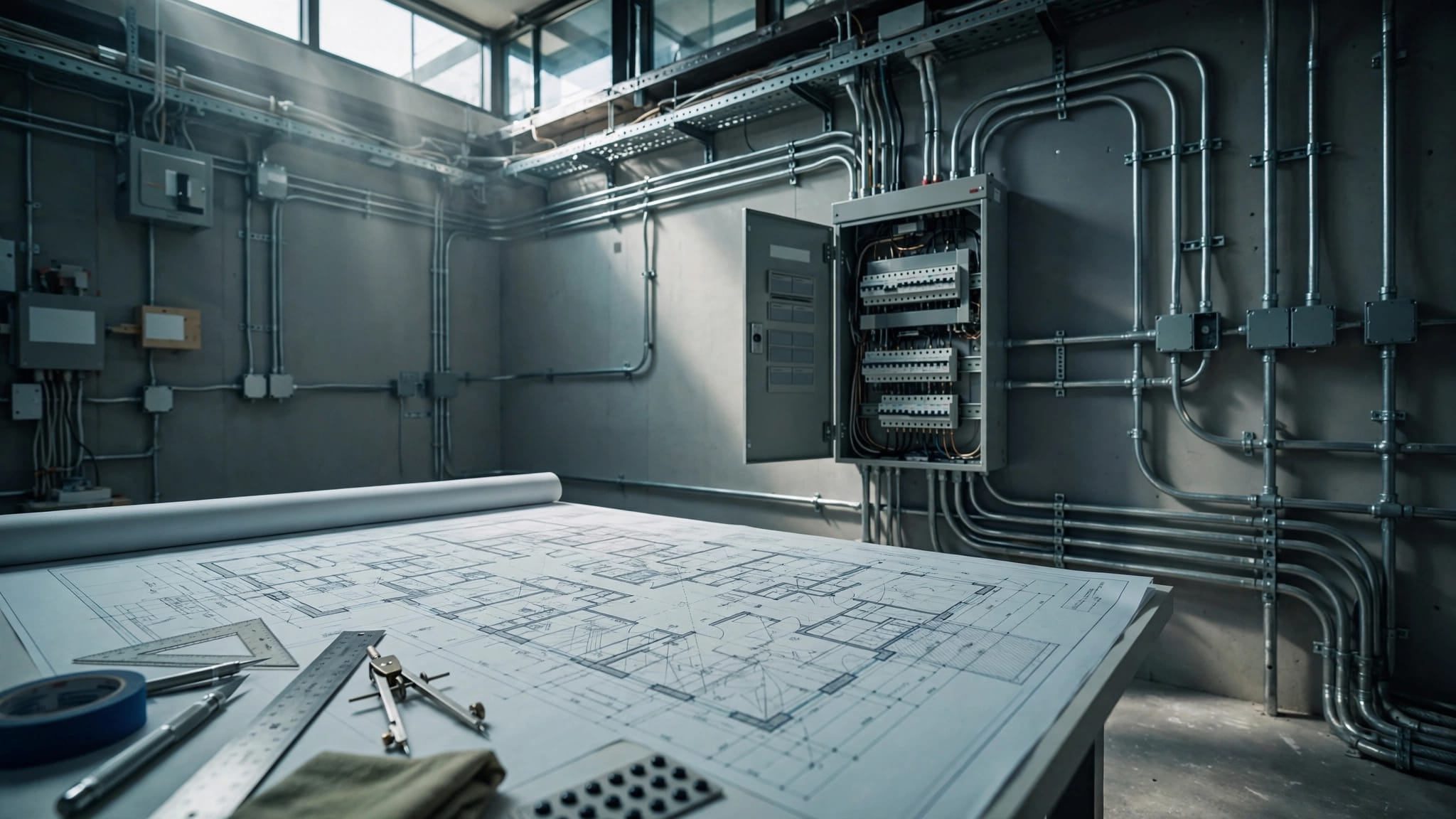
A moved outlet or rerouted feeder can turn an old drawing into an expensive guessing game. A commercial electrical as-built plan should document the finished installation , so future electricians don't have to reconstruct what happened during construction.
For business owners and property managers, that means reliable equipment locations, circuit references, and wiring routes. The drawings should reflect field conditions, rather than repeat the original design.
Start by understanding what makes an as-built record different from a construction plan.
What a commercial electrical as-built plan records
Original design drawings show the intended installation. As-built documentation records what the contractor installed, including changes made during construction.
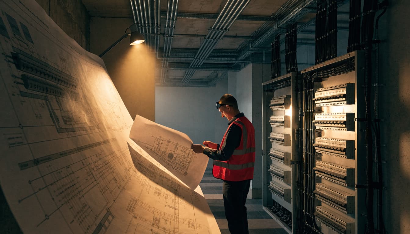
That distinction matters when a panel moves, equipment changes, or a conduit follows a different path around existing ductwork. A design sheet stamped "as-built" without those updates leaves the owner with inaccurate information.
Projects use the terms "as-built drawings" and "record drawings" differently. The contract should identify who records field changes, who prepares the final set, and how much detail the owner receives.
A useful set may include floor plans, panel schedules, equipment schedules, distribution diagrams, and installation details. However, those aren't universal deliverable requirements. The project scope, contract, and applicable review requirements determine the final package.
For owners planning commercial electrical installation and upgrades, documentation belongs in the written scope before work begins. That makes responsibility clear while the installation is still visible.
Installed equipment and device locations
The plan should help an electrician find equipment and understand what it serves. Locations need enough detail to distinguish nearby devices.
Power distribution and connected equipment
Document installed service equipment, meters, panelboards, transformers, disconnects, and major electrical loads within the project scope. Where generators or transfer equipment are included, show their locations and relationships to the distribution system.
Equipment tags should match the physical labels and schedules. Record verified manufacturer and model information where the closeout scope calls for it, along with relevant voltage, phase, and ratings.
Also distinguish new equipment, retained existing equipment, and equipment removed or abandoned. A symbol left over from the original drawing can otherwise suggest that a disconnected installation remains operational.
Lighting, receptacles, and related systems
Show installed receptacles, switches, lighting fixtures, controls, and dedicated equipment connections. Include sign power, point-of-sale connections, and HVAC disconnects where they form part of the work.
Lighting documentation should identify actual control zones, sensor locations, and daylight-control relationships. Emergency lighting and exit signs also need clear identification within the agreed scope.
Data, security, access control, and fire alarm systems may have separate drawings. Cross-reference them rather than leaving their power connections unexplained. These systems often overlap during commercial tenant fit-out electrical planning, so their final records should agree.
Panel schedules and circuit identification
A commercial electrical as-built plan should connect each documented load to the equipment supplying it.
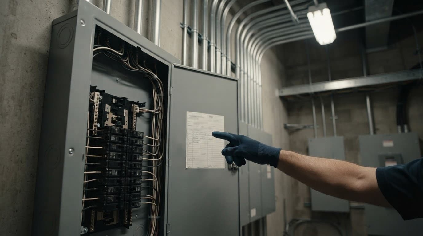
Match circuit references to physical labels
Use consistent panel names across floor plans, distribution diagrams, panel schedules, and equipment labels. Circuit numbers on device callouts should match the installed breaker positions and final directory.
Descriptions should identify the actual area or equipment served. A refrigerator, exhaust fan, or sales-floor lighting zone needs a recognizable description rather than a vague equipment number.
Where a circuit serves multiple areas, document that relationship. Conversely, don't assume that every receptacle in one room shares a circuit. Field verification should resolve the connections before the contractor finalizes the schedule.
Record ratings without overstating capacity
Depending on the agreed detail, schedules should record panel ratings, system voltage and phase, breaker ratings, pole counts, and connected loads. Feeder information should agree with the distribution diagram and installed equipment.
Distinguish a spare breaker from an empty breaker position. Neither one, by itself, proves that the service has capacity for additional equipment.
If installed equipment changes the electrical demand, the project team should review the affected load calculations. The final documentation should reference those updated calculations where they belong in the closeout package.
Wiring and conduit routes that reflect the field
Routes matter most when ceilings, walls, or pavement hide the installation. A straight line on a drawing can mean several different things.
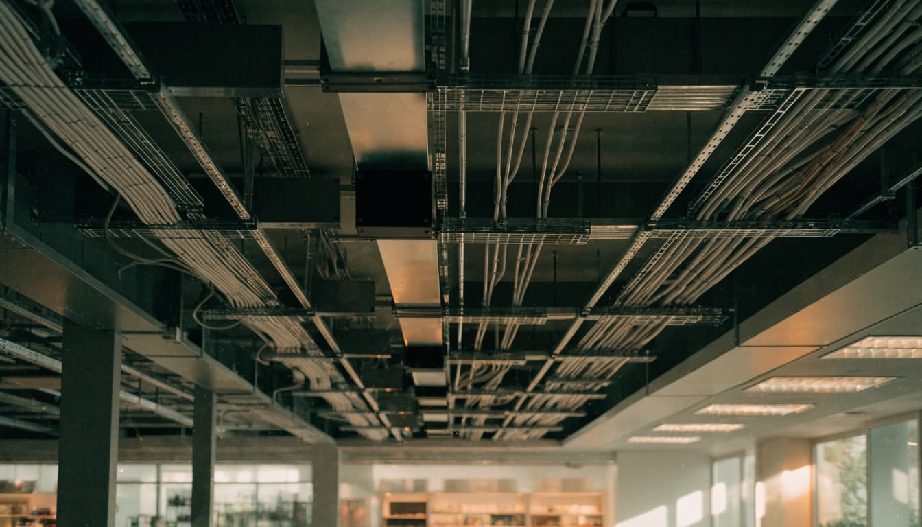
Separate schematic connections from actual paths
Identify whether a line shows an electrical connection or a verified physical route. A single-line diagram explains distribution relationships, but it doesn't necessarily locate conduit inside the building.
For documented feeders and raceways, record endpoints, major direction changes, junction or pull boxes, and transitions between floors. Include conduit size, wiring method, and conductor information where the project scope requires that detail.
Useful location references include room numbers, structural grids, and dimensions to permanent features. Ceiling tiles, displays, and movable shelving make poor reference points because their positions can change.
Capture concealed and coordinated pathways
Record concealed routes before finishes cover them. Underground routes deserve particular attention because later excavation depends on reliable location information.
Dated photographs can support the drawings, especially at penetrations, junction points, and unusual bends. However, a photo without a location reference can be difficult to interpret later.
Coordinate electrical pathways with ductwork, plumbing, refrigeration lines, and rated assemblies. Where communications pathways are included, document their destinations and access points. Keep their identification separate from power wiring so future technicians understand which system each pathway serves.
Changes from the approved design
Field changes are often the most valuable part of the final record. They explain why the finished building differs from the construction drawings.
Capture relocated devices, substituted equipment, revised circuit assignments, rerouted feeders, and added or deleted work. If a disconnect moves to preserve service access, both its location and its related callouts need updating.
Changes can affect several sheets at once. An equipment substitution may alter the floor plan, panel schedule, distribution diagram, and equipment schedule. Updating only one sheet creates conflicting instructions.
Reference approved change documentation where appropriate, including relevant requests for information or revised drawings. The final set should also identify its issue date and revision status.
Recording a change doesn't establish its approval or code compliance. Required reviews and inspections remain separate. For retail projects, confirm the applicable municipal process alongside Massachusetts retail electrical requirements, especially when service equipment or life-safety systems change.
Clear legends, annotations, and sheet references
Even an accurate drawing becomes difficult to use when its symbols or abbreviations are unclear. The legend should explain the symbols actually used in the final set.
Define device types, equipment tags, circuit notation, and line conventions. If different line styles identify concealed routes, existing work, or emergency systems, explain those distinctions consistently.
Annotations should describe field conditions without forcing readers to guess. Note installation heights where they matter, unusual mounting arrangements, access requirements, and connections that aren't obvious from the floor plan.
Sheet references should lead to the correct detail or schedule. Also remove obsolete notes that describe work the contractor didn't install.
A verified route and a schematic connection should never look interchangeable without a legend explaining the difference.
Use legible text at the intended print size. Keep room names and numbers aligned with the final architectural drawings, because equipment references become confusing when electrical and architectural plans name the same space differently.
Field verification and the final handover
Accuracy depends on when the contractor collects information and how the team checks it. Memory at closeout is a poor substitute for ongoing records.
Update the drawings while work remains visible
Maintain field markups throughout construction, then transfer confirmed changes into the final drawings. Photograph concealed work before closure and connect each image to a drawing location.
Before handover, walk the completed space with the current drawings and equipment schedules. Compare device locations, panel labels, disconnects, circuit directories, and equipment identification.
Check the finished layout, too. Shelving, inventory, cabinetry, and mechanical equipment can obstruct access that looked adequate during rough-in. Drawings should reflect the installed arrangement, while the project team addresses any access problems through the proper review process.
Deliver one coordinated, usable record
Agree on file formats before closeout. Owners may request a readable PDF, editable drawing files, or both, depending on the contract and future maintenance needs.
Keep drawings with relevant product information, test reports, permit records, and inspection documentation. Emergency lighting, lighting controls, and changed fire alarm systems may have supporting test records separate from the plans.
Identify unresolved documentation gaps instead of disguising assumptions as verified conditions. Also remember that drawings don't replace safe electrical work procedures. A qualified electrician must verify conditions and follow proper isolation procedures before working on equipment.
Key Takeaways
A dependable final record gives the next electrician a useful starting point:
- Document installed equipment and devices with consistent locations, tags, and schedule references.
- Match panel directories and circuit callouts to verified field connections.
- Explain actual routes, design changes, and drawing conventions without hiding uncertainty.
The owner should also receive a clearly dated final set, with responsibility assigned for future updates after renovations or equipment replacements.
Frequently Asked Questions
Does an as-built plan prove the installation passed inspection?
An as-built plan records installation information. It doesn't independently establish inspection approval or certify code compliance.
Keep permit and inspection records alongside the drawings, rather than treating the drawing title as proof of acceptance. Likewise, an inspection approval doesn't mean every route or circuit reference in the documentation is accurate. The contractor still needs to check the final record against the field.
Should an existing building have every circuit mapped?
The agreed scope determines how much of the existing system the project documents. A tenant renovation may cover only the affected space and its supplying equipment.
However, the drawings should make those boundaries clear. Identify existing circuits affected by the work and distinguish verified information from areas outside the survey. If the owner needs a building-wide circuit map, include that investigation in the written scope.
Conclusion: Make the Record Match the Building
A commercial electrical as-built plan earns its value through verified field information . Accurate equipment locations, circuit identification, and clearly described routes reduce the guesswork that outdated drawings create.
Ask your contractor to define the documentation scope before construction and check the final set against the completed installation. Then keep it current after electrical changes, so the next repair or renovation starts with a record your electrician can trust.