

Commercial Access Control Wiring for Greater Boston Buildings

Contact Us
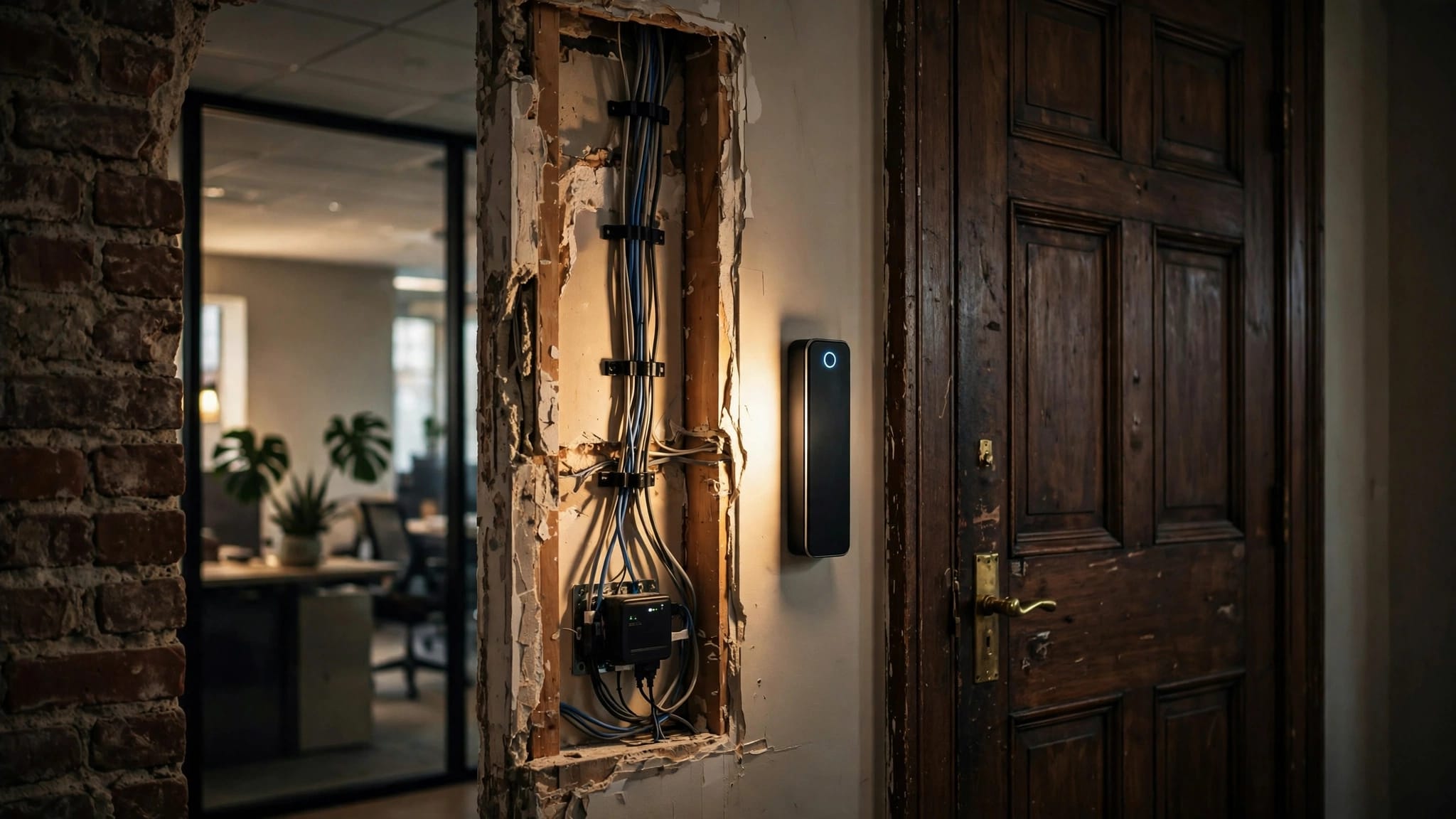
A reliable access system depends on more than readers and cards. The wiring has to match each door, reach the control equipment safely, and work with the building's other systems.
In Greater Boston, retrofits can involve old masonry, finished ceilings, and years of undocumented changes. Good access control wiring planning accounts for those conditions before walls close or hardware is ordered.
Start with the opening and its hardware, then coordinate routes, power, and system interfaces.
Plan access control wiring around the existing building
A retrofit begins with a careful look at each opening. Record the door type, frame material, swing, existing lock, nearby power, and access to the ceiling or wall cavity. Note where the system's controller and power supply will sit, too.
In older commercial buildings, cable may need to pass through plaster, masonry, or areas altered by past renovations. A route that appears clear on a drawing may be blocked by ductwork, piping, or structural elements.

Survey openings before choosing routes
Walk the proposed path from each reader and lock to the controller. Look for accessible ceiling spaces, existing raceways, suitable wall cavities, and places where cables can be supported and serviced later. If a route crosses a finished or shared area, include that condition in the project plan.
Also identify the number of controlled doors and the devices planned at each one. A card reader alone needs a different set of connections than a reader paired with a powered strike, door contact, and request-to-exit device.
Set the scope before rough-in
Define which contractor supplies and pulls cable, who installs sleeves or raceways, and who handles terminations and testing. Include deadlines for rough-in, ceiling closure, equipment installation, and system testing.
This coordination helps prevent substitutions at the last minute. For broader projects, commercial wiring and security system services should be considered alongside the electrical plan, not after the walls and ceilings are finished.
Match reader cable to the system protocol
Reader wiring depends on the selected device and communication method. For example, HID Signo readers support Wiegand and OSDP connections, but the cable requirements differ. The product's installation instructions should guide the specific cable and termination plan.
Wiegand installations commonly need five to ten conductors. HID's Signo guide lists maximum distances of 500 feet with 18 AWG wire and 300 feet with 20 AWG wire. Those figures are specific to the guide and reader installation, not a universal limit for every access system.
OSDP uses a different cable arrangement
HID specifies four-conductor, twisted-pair, overall-shielded, UL-approved cable for OSDP, such as Belden 3107A or an equivalent. The guide calls for 120-ohm ±2% termination across the RS-485 bus ends on runs longer than 200 feet, or where electromagnetic interference is present.
Because readers, controllers, and cable routes vary, use the chosen system's documentation when laying out conductors and termination points. Avoid assuming that a cable suitable for one protocol will automatically suit another.
Keep the reader run serviceable
Make terminations in accessible locations and identify cables at both ends. Leave enough service loop for future replacement without stuffing excess cable into a box or door frame. Labeling and consistent routing also make troubleshooting easier when a building adds doors or changes its access software.
Choose door hardware before pulling cable
The lock determines the wiring requirements at the opening. An electric strike, magnetic lock, and electrified lockset each have different power and release needs. The door and frame must also be suitable for the selected hardware.
A typical controlled opening may include an exterior reader, an electric strike or lock, a door-position contact, and an interior request-to-exit device. The controller needs the right conductors for those functions, and each device needs a planned mounting location.

Plan the lock and frame together
Retrofitting an electric strike can require modifying the frame and selecting a compatible faceplate. The HES 5200 Series instructions also distinguish fail-secure and fail-safe operation. That choice affects what happens to the exterior lock when power is lost, so it belongs in the door and life-safety design.
A latchbolt-monitor contact, when included, reports the latch position. A door-position contact reports whether the door is open or closed. They provide different information, and one should not be treated as a substitute for the other.
Size power wiring for the actual strike
The HES 5200 guide lists intermittent-duty current of 0.24 A at 12 VDC and 0.12 A at 24 VDC. Its wire-gauge recommendations use the round-trip cable length, which matters when calculating voltage drop.
| Round-trip run | 12 VDC minimum | 24 VDC minimum |
|---|---|---|
| Up to 200 ft | 18 AWG | 20 AWG |
| 200 to 300 ft | 16 AWG | 18 AWG |
| 300 to 400 ft | 14 AWG | 16 AWG |
These values apply to the HES 5200 guidance, not every electric strike. A strike's rated voltage and supply also matter, since the manufacturer warns that voltage more than 10% above the solenoid rating can cause severe damage.
Route cables through protected, accessible pathways
Access-control cables should follow a planned route that protects them from damage and leaves them reachable for service. Depending on the building, that route may use conduit, sleeves, cable tray, J-hooks, or a dedicated raceway.
Keep communications cabling separated from line-voltage wiring according to the applicable installation requirements. Where a crossing is needed, plan it deliberately rather than running both systems together without control. Support cables from the building structure, not ceiling tiles, sprinkler pipe, ducts, or other building services.
Penetrations through rated assemblies need an appropriate firestop method. Record the route, serving area, wall or floor penetrations, and equipment destination on the project drawings. This becomes especially useful when a later renovation puts new trades above the same ceiling.
For retail projects, include card readers and security cabling with the wider retail buildout electrical planning, including fire alarm devices, lighting, partitions, and ceiling work.
Coordinate access control with other building systems
The access system may share equipment spaces and pathways with cameras, alarms, network hardware, and building systems. However, each system can have separate cables, power sources, enclosures, and testing needs. A coordinated plan identifies these needs before contractors compete for limited space.
An access-control controller may need a suitable location with room for terminations and maintenance. Coordinate its power, grounding and bonding, ventilation, and service access with the electrical and technology teams. Leave space for planned equipment rather than packing the enclosure or rack at the start.
Treat the fire alarm interface as a separate design task
Some access systems interact with the building fire alarm or other life-safety equipment. The required interface and sequence depend on the project and devices. The reader or door contractor should coordinate that work with the fire alarm contractor instead of treating the connection as an ordinary access-control input.
Changes to alarm interfaces should be included in the project schedule and testing plan. When the project includes an alarm upgrade, coordinate it with commercial fire alarm installation so device locations, power, pathways, and final tests align.
Coordinate cameras and network equipment
Cameras may use nearby pathways or share a communications closet with access-control equipment. Plan cable routes, equipment space, and access to service points together. The same applies to network connections that carry reader or controller communications.
For projects adding cameras at entrances, commercial security camera wiring options can inform pathway planning without conflating camera connections with lock power or reader wiring.
Schedule the trades before walls and ceilings close
Electrical contractors, low-voltage installers, security integrators, general contractors, and building staff all affect the finished route. A coordination meeting before rough-in should settle who supplies cable, installs pathways and sleeves, completes firestopping, terminates devices, and tests the system.
Also agree on the sequence. The electrical and low-voltage teams need access before ceilings close, while door and frame work may have its own timing. HVAC ducts, plumbing, sprinklers, lights, and structural elements can all force cable rerouting if their locations change after rough-in.
On occupied properties, schedule noisy or disruptive work around business operations. Identify which doors must remain usable, how workers will access controlled areas, and whether a temporary entry procedure is needed during the cutover.
Greater Boston buildings can have constrained service areas and shared corridors. As a result, the plan should identify access limits and restoration work early, especially where cabling passes through tenant spaces or common areas.
Test the system and document what was installed
Before handoff, test each reader, lock, contact, and exit device in the configuration the building will use. Confirm that credentials produce the intended response, that door status reports correctly, and that the lock behaves as designed during normal operation and the planned release sequence.
Testing should include the system interfaces covered by the project, including alarm connections when present. The security integrator and fire alarm contractor should coordinate their portions of the test. Keep the test records with the equipment information and maintenance documents.
As-built drawings should show the installed pathway, cable identifiers, device locations, controller and power-supply locations, and any significant changes from the original plan. Good commercial electrical as-built drawings help future technicians find concealed routes without reopening finished surfaces.
Key takeaways
- Survey every opening and cable route before selecting hardware or starting rough-in.
- Match reader cable and termination details to the chosen protocol and manufacturer.
- Size lock power conductors for the specific device, voltage, and round-trip distance.
- Keep pathways supported, protected, separated as required, and accessible for service.
- Coordinate access control with electricians, security, fire alarm, network, and construction teams.
- Test the installed devices and preserve clear as-built records.
FAQ
Can an existing commercial door be converted to card access?
Often, but the frame, lock, door condition, and available cable route determine the work. An electric strike retrofit, for instance, may require a frame cutout and a compatible faceplate. The hardware must also fit the door's intended operation.
Is OSDP wiring the same as Wiegand wiring?
No. HID's Signo guidance describes different conductor and cable arrangements. OSDP uses a four-conductor twisted-pair cable with an overall shield, while Wiegand commonly uses five to ten conductors. Follow the specific reader and controller instructions.
Does every controlled door need a door contact?
That depends on the system's monitoring requirements. A door-position contact reports whether the door is open or closed. A lock's latchbolt monitor reports the latch position, so the two devices provide different information.
Can the access system connect to the fire alarm?
Some designs include an interface, but its wiring and operation must be planned for the specific system and building. Coordinate the access-control and fire-alarm contractors so the agreed interface is included in installation and testing.
Plan the wiring before the retrofit
A dependable access system starts with a well-planned route and hardware that suits each opening. In Greater Boston buildings, early coordination also helps account for older construction, shared pathways, and other systems already in place.
When cable type, lock power, trade responsibilities, and testing are settled before close-in, the finished installation is easier to service and less likely to need avoidable rework.